


Infrastructure Test in the 2‑Nanometer Era: ASML's Lithography Machine Drives a Leap in Cleanroom Scale
Infrastructure Test in the 2‑Nanometer Era: ASML's Lithography Machine Drives a Leap in Cleanroom Scale The semiconductor industry’s push into the 2-nanometer node isn’t just a materials or process challenge—it’s an infrastructure inflection point.
The semiconductor industry’s push into the 2-nanometer node isn’t just a materials or process challenge—it’s an infrastructure inflection point. ASML’s latest high-NA EUV lithography systems demand unprecedented environmental control: vibration isolation within ±5 nanometers, temperature stability of ±0.1°C, and airborne molecular contamination (AMC) levels measured in parts-per-quadrillion. These requirements cascade directly into cleanroom design, forcing manufacturers to re-evaluate every element—from clean room classifications to wall assembly, ceiling integration, and utility routing. For electronics and semiconductor fabs scaling production at this frontier, cleanroom engineering is no longer a supporting function; it’s a core enabler of yield, throughput, and technology leadership. This shift places new pressure on clean room manufacturers, system integrators, and component suppliers to deliver solutions that are not only compliant but future-proofed for next-gen toolsets. In this context, selecting the right cleanroom supplies, validating airflow integrity, and aligning modular architecture with tool footprint become strategic procurement decisions—not just facility upgrades.
Section 1: From Class 100 to Sub-Class 10—Redefining Cleanroom Classifications for EUV Integration
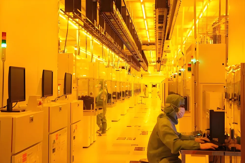
ASML’s high-NA EUV scanners operate in environments where even trace particulates can cause pattern collapse or overlay errors. While legacy fabs often relied on class 100 clean room (ISO Class 5) zones for photolithography bays, today’s 2-nm pilot lines require localized sub-class 10 (ISO Class 4) or even ISO Class 3 conditions directly around the tool footprint. This isn’t theoretical—it’s operational reality. Achieving such stringent clean room classification demands holistic recalibration across three layers: air handling, structural envelope, and surface integrity.
Air distribution must shift from conventional top-down laminar flow to hybrid configurations—often combining ultra-low penetration air (ULPA) ceiling modules with perimeter recirculation walls and underfloor return plenums. The Pharmaceutical cleanroom ceiling—though named for life sciences—has become a benchmark for semiconductor-grade ceilings due to its leak-tight gasketed panel design, integrated lighting, and seamless integration with FFUs (fan filter units). Similarly, pharmaceutical clean room panels are increasingly specified for fab tool enclosures: non-shedding, electrostatic-dissipative (ESD) aluminum composite cores with smooth, cleanable surfaces that resist chemical outgassing during solvent-based cleaning cycles.
Structural integrity extends to viewing interfaces. Double glass window panes—with inert gas fills and conductive coatings—are now standard for EUV tool observation ports. They provide thermal stability, EMI shielding, and particle-free visibility while maintaining pressure differentials between adjacent zones. And because tool maintenance windows are tightly scheduled, access points must be both secure and rapid: cleanroom classifications compliance hinges on pass-throughs like the aluminum pass box, engineered for ISO Class 4 integrity with interlocked doors, UV sterilization, and HEPA filtration.
Ultimately, the move beyond class 10000 clean room (ISO Class 7) buffer zones reflects a broader trend: classification is no longer uniform across a bay. It’s zoned, layered, and dynamically managed. That means your clean room design must support variable pressure cascades, real-time particle monitoring at tool-level, and rapid requalification after maintenance—making modular, validated components essential, not optional.
Section 2: Modular Precision—How Standardized Components Accelerate Fab Ramp-Up
In semiconductor manufacturing, time-to-volume is a competitive differentiator—and traditional stick-built cleanrooms can delay ramp-up by 6–9 months. Modular cleanroom systems have emerged as the preferred solution for EUV integration zones, offering factory-certified performance, reduced on-site labor, and full traceability of materials and testing. But “modular” doesn’t mean generic. It means purpose-engineered components designed for semiconductor-grade reliability and interoperability.
Take wall systems: pharmaceutical clean room panels are now widely adopted not for pharma use—but for their certified low-VOC emission profiles, dimensional stability under humidity cycling, and compatibility with aggressive peroxide and ozone decontamination protocols. These same panels integrate seamlessly with structural framing that supports dynamic load requirements of multi-ton lithography tools—without transmitting micro-vibrations.
Ceilings follow suit. A Pharmaceutical cleanroom ceiling system—featuring pre-wired ULPA modules, integrated fire-rated dampers, and tool-access hatches—cuts installation time by up to 40% versus field-assembled grids. And when paired with double glass window panes that match panel thickness and gasket profiles, visual inspection zones maintain consistent pressure decay rates and particle ingress resistance.
Then there’s workflow-enabling hardware. A cleaning station isn’t just a sink—it’s a fully contained, stainless-steel, HEPA-filtered workstation with programmable rinse cycles and conductivity monitoring, used for wafer carrier and reticle pod decontamination before tool entry. Likewise, cleanroom equipment such as laminar flow hoods must meet ISO 14644-1 Class 3 criteria at the work surface—critical for mask handling and metrology prep. The clean laminar flow hood, for example, delivers vertical airflow at 0.45 m/s ±10%, with zero turbulence at the working plane—validated per IEST-RP-CC002.3.
Even mobility matters. With tools requiring frequent calibration and optics servicing, moving equipment without compromising zone integrity is vital. That’s why vehicle-mounted laminar hoods—like the moving laminar hood vehicle—are gaining traction: they combine ISO Class 3 airflow with castor-based maneuverability, enabling on-demand sterile zones anywhere in the bay. These aren’t add-ons—they’re mission-critical clean room supplies that keep 2-nm production lines running.
Section 3: Selecting the Right Clean Room Manufacturers for Semiconductor-Scale Projects
Choosing a clean room manufacturers partner for a 2-nm node project isn’t about comparing brochures—it’s about verifying execution capability at scale. Semiconductor fabs demand more than ISO certification; they require partners who understand tool OEM interface requirements, fab utility standards (e.g., SEMI F57), and the audit rigor of global IDM quality systems.
Start with validation depth. Leading clean room manufacturers don’t just test airflow velocity—they perform full-scale, third-party ISO 14644-3 certification on complete module assemblies, including pressure decay, particle count mapping, and recovery testing post-intervention. They also maintain traceable material logs: every gasket, sealant, and panel batch is documented for outgassing data (per ASTM E595), flame spread (ASTM E84), and ESD performance (ANSI/ESD S20.20).
Second, assess supply chain resilience. With lead times for EUV-compatible components stretching beyond 24 weeks, manufacturers must hold strategic inventory—especially for high-precision items like double glass window panes with anti-reflective, conductive coatings or custom-sized Pharmaceutical cleanroom ceiling modules. Look for suppliers with dual-sourcing agreements and regional warehousing—critical when a single delayed shipment could stall tool commissioning.
Third, evaluate integration support. Does the supplier offer turnkey services—including HVAC interface engineering, seismic anchoring design, and cleanroom commissioning support aligned with ASML’s site acceptance test (SAT) protocol? Can they co-locate engineers during tool install to troubleshoot airflow interference or pressure imbalance in real time? The acrylic clean booth, for instance, may serve as a temporary metrology enclosure—but only if its design accounts for tool exhaust backpressure, floor loading, and integration with fab-wide BMS systems.
Finally, consider lifecycle partnership. Semiconductor nodes evolve rapidly. Your clean room design should allow for retrofitting—whether upgrading FFUs to higher-efficiency ULPA filters, adding AMC scrubbers, or expanding pass-through capacity. Suppliers who offer digital twin modeling, change-order agility, and post-installation performance monitoring are positioned to support your roadmap—not just your current build.
Frequently Asked Questions
Q1: What cleanroom classification is required for ASML’s high-NA EUV lithography tools?
ASML specifies localized ISO Class 3 (equivalent to class 100 clean room in older Fed-Std-209E terms) conditions directly around the scanner’s optical column and reticle stage. Surrounding tool service zones typically require ISO Class 4–5, while general fab bays may operate at ISO Class 7 (class 10000 clean room). Full compliance requires zoned pressure cascades, real-time particle monitoring, and validated recovery times under 20 seconds after door opening—verified per ISO 14644-3.
Q2: Can pharmaceutical-grade cleanroom components be used in semiconductor fabs?
Yes—and they’re increasingly preferred. Pharmaceutical clean room panels and Pharmaceutical cleanroom ceiling systems meet or exceed semiconductor requirements for low outgassing, surface smoothness, and cleanability. Their certified VOC profiles, ESD-compliant finishes, and gasketed construction make them ideal for EUV tool enclosures and metrology bays. Just ensure the supplier validates performance against SEMI standards—not just ISO or USP <797>.
Q3: How do double glass window panes improve cleanroom performance in lithography areas?
Double glass window panes provide critical thermal, acoustic, and particulate isolation. The sealed argon or krypton fill minimizes convective currents at the viewport—preventing localized turbulence that could disturb laminar flow. Conductive coatings enable static dissipation, while laminated construction meets impact and fire-rating requirements. In practice, they reduce particle ingress through observation points by >90% versus single-pane alternatives and support stable differential pressures across ISO Class 3/4 boundaries.