







Cleanroom Semiconductor Fab Infrastructure for the 2-Nanometer Era: Scaling Around ASML Lithography Systems
Plan 2 nm fab infrastructure around lithography with cleanroom zoning, airflow, utilities, vibration control, commissioning, and scalable capacity.
Why Advanced Lithography Changes Fab Infrastructure
A cleanroom semiconductor fab supporting 2-nanometer production must be planned around the lithography tool and its supporting processes, not around a generic room classification. Advanced scanners, metrology platforms, coat-and-develop tracks, and material-handling systems create tightly coupled requirements for particles, airborne molecular contamination, temperature, humidity, vibration, utilities, and service access. A small disturbance that would be acceptable in a conventional electronics room can affect alignment, focus, or process repeatability near an advanced lithography cell. The facility team therefore needs a coordinated design basis that translates tool requirements into measurable room, structural, and mechanical performance.
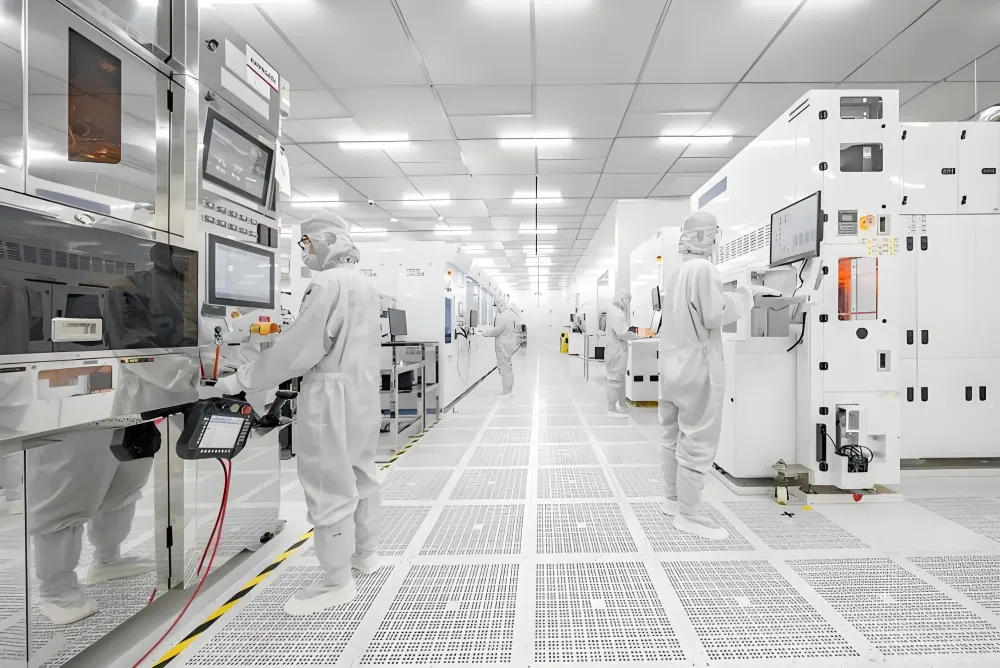
Zoning should separate the most sensitive exposure and metrology functions from support corridors, chemical delivery, maintenance routes, and less critical production steps. Instead of applying the highest class everywhere, the design can use nested zones with tighter control around the scanner and reticle path. These cleanroom classifications must be connected to actual operating states, including production, idle periods, maintenance, and recovery after an intervention. Personnel and material routes should minimize crossing, while service access should allow technicians to reach utilities and equipment components without opening large sections of the cleanest environment.
Vibration and thermal stability need equal attention. Tool pedestals, floor systems, ducts, pumps, and nearby traffic can transmit movement into alignment-sensitive equipment. Structural analysis should address both steady vibration and intermittent events such as door movement or material transport. Heat released by tools, motors, lighting, and operators must be removed without creating unstable air currents. The project team should reserve capacity for future tools because adding heat or exhaust after commissioning can disturb pressure relationships and airflow distribution across the bay.
Utility coordination is another critical constraint. Process cooling water, power, gases, vacuum, exhaust, controls, and data connections should arrive at the tool through planned service zones with accessible isolation points. Penetrations must be sealed and detailed to avoid particle traps. Redundant utilities may be justified where a short interruption could damage product or require lengthy tool recovery. Monitoring points should be placed where they reveal conditions at sensitive interfaces rather than only providing a room average that hides local drift.
Coordinating Ceilings, Airflow, and Tool Interfaces
The clean room ceiling requirements for a lithography bay extend beyond supporting filters and lights. The ceiling grid must remain level, sealed, and stable while carrying filtration modules, fire protection, sensors, and maintenance loads. Access panels should be arranged so service work does not release debris above exposed processes. Seismic restraint, gasket compatibility, and penetration details require coordination before fabrication. A ceiling that is assembled from individually acceptable components can still fail to perform if tolerances, seals, and utility interfaces are not managed as one system.
A modular clean room ceiling system can shorten installation and simplify later reconfiguration, but module boundaries should follow the airflow plan and tool layout. Filter coverage, supply velocity, return locations, and equipment exhaust must work together to move contaminants away from critical surfaces. A ceiling-mounted fan filter unit provides flexible filtered-air delivery, yet installing more units does not automatically improve performance. Poorly located returns or tall equipment can create turbulence, short-circuiting, and stagnant pockets even when total airflow appears adequate.
Materials around the tool should be low-shedding, cleanable, chemically compatible, and stable under temperature and humidity cycling. Wall panels, windows, doors, floors, and sealants need documented performance appropriate to the process. A clean room semiconductor environment also requires control of molecular contaminants released by construction products, lubricants, plastics, and cleaning agents. Material review should occur before procurement so emissions or chemical incompatibility are not discovered after the scanner has been installed.
Tool interfaces need clear ownership. The cleanroom contractor, lithography equipment supplier, facility designer, automation team, and commissioning authority should agree on boundaries for airflow, utilities, vibration, exhaust, monitoring, and acceptance testing. Interface drawings and responsibility matrices prevent gaps in which each party assumes another will provide a required control. Mock-ups or coordinated digital models can expose access conflicts before fabrication and help confirm that maintenance tools, replacement filters, and lifting paths fit the completed space.
Commissioning for Stable Production and Future Scaling
Commissioning should verify the facility as an integrated operating system. Testing typically covers airflow quantity, filter integrity, pressure differentials, temperature, humidity, recovery behavior, particle conditions, vibration, alarms, and utility stability. Airflow visualization can show how clean supply air moves around the scanner, transfer equipment, and operator positions. Test states should be agreed in advance so results reflect realistic production and maintenance conditions. Deviations should be investigated across the whole system rather than corrected through isolated adjustments that create another problem elsewhere.
Continuous monitoring allows the operating team to detect drift before it affects yield. Pressure, environmental conditions, particles, vibration, and selected molecular contaminants can be trended alongside tool events and maintenance activity. Alarm limits should reflect process risk and normal variation. A practical response plan defines who reviews an alarm, how potentially affected material is identified, which facility checks are required, and what evidence permits the area to return to service. This connection between facility data and production decisions turns monitoring into an operational control rather than a dashboard.
Expansion planning should begin before the first production lot. Air-handling systems, electrical distribution, utility headers, controls, and service corridors can be divided into zones so new capacity is installed with limited disruption. Isolation points and temporary barriers should support construction beside operating areas. Spare capacity must be real and documented, not an assumption based on unused physical space. When the architecture, ceiling, airflow, utilities, monitoring, and commissioning strategy are coordinated from the start, advanced lithography infrastructure can support stable production today and a practical path to the next tool generation.